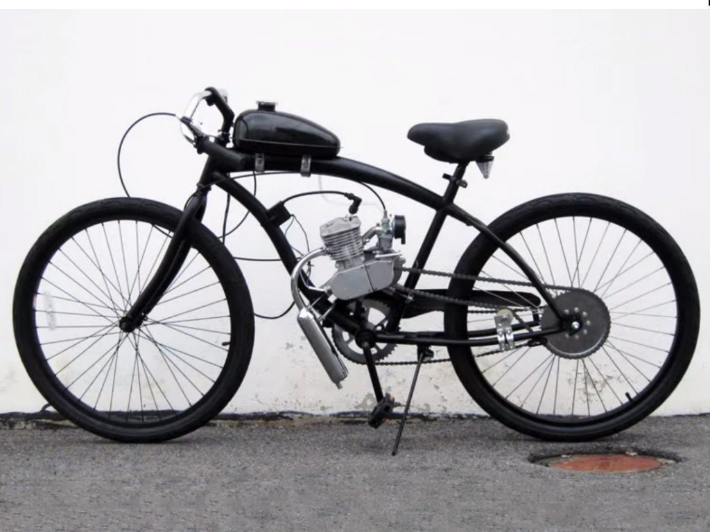
2-Stroke Bike Engine Kit
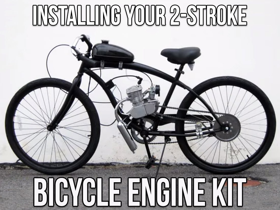
Installing Your 2-Stroke Bike Engine Kit
Here we’ll instruct you on how to install a two-stroke bicycle engine kit on a bike. Now, before we even start, it’s important to know what you’re getting into and what you need to make sure installation goes as smooth as possible.
First things first- The Bike:
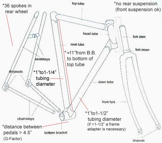 Even though the engine kit is made to be as universal as possible a few key features your bike should have will make installation a lot easier:
- Your bike needs to be a standard male beach cruiser, road or hardtail mountain bike.
- The tubes should be 25 to 28mm in diameter with an open “V” style frame
- The frame should also have 9-11 inch of clearance between the bottom bracket and top bar.
- These kits will fit most 26”x 1.75” wheel with a standard 12 or 14 gauge 36 count spoke
- If you’re in these right specifications then you’re good to go!
Sprocket and Wheel Clamp Assembly:
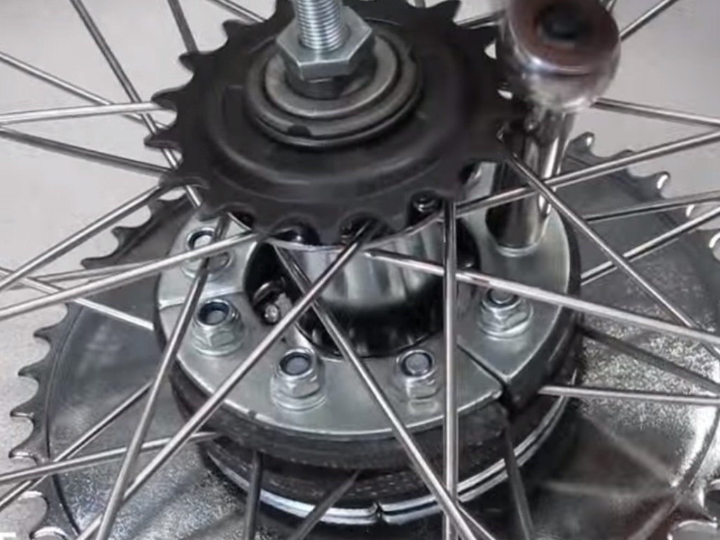 Most sprocket clamp assemblies comes with 9 bolts and nuts, two rubber grommets, and a single pair of metal plates (though some engine kits may have two). Most clamp assemblies come with 10mm bolts and studs, so you’ll need a socket wrench to complete this part of the installation.
If you’re using a coaster brake, first start by removing the coaster brake arm
(be careful not to accidentally disassemble the entire axle).
- Cut a straight line in between two of the holes on one of grommets (not both)
- Thread the grommet through the wheel around the hub (Note: Make sure the grommet holes are between the spokes, not blocking them)
- Take the metal plates from your assembly and align them on top of the grommet inside of the wheel, then align the sprocket with the grommets to make sure the spokes and grommet holes are aligned
- Starting from the inside of the wheel, send each bolt through the grommet and sprocket, and torque them down (Note: It will help to torque them in a star-shaped pattern)
Once you’re done tightening down the sprocket and clamp assembly, put the wheel on the bike and bolt it down with good tension on the bicycle chain.
Note: We highly recommend using caliper or disc brakes even if you have a coaster brake wheel. Because of the speeds you’ll be getting up to, you’ll want to be sure to have additional stopping power than a coaster brake.
Mounting the Engine:
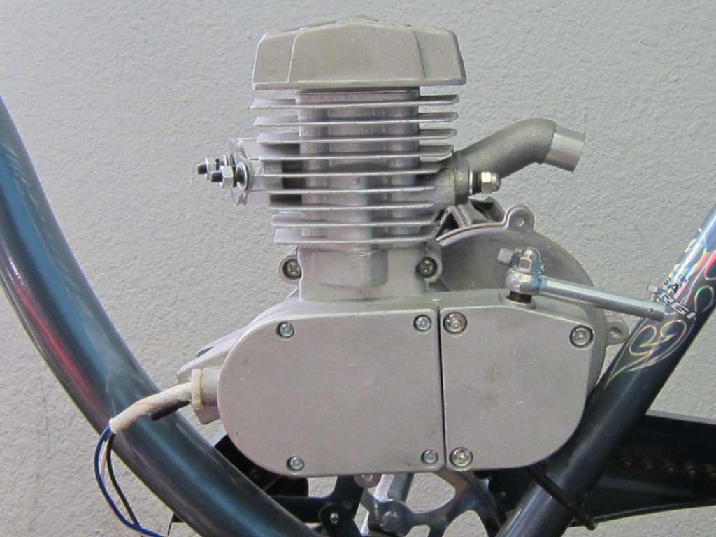 Mounting the engine is actually a pretty easy procedure, but if your frame’s not as described above, there are a few things you’re going to need to install before mount the motor.
If you’re using a universal u-mount and/or vibration motor mounts to compensate for a larger downtube and/or seat tube, you’ll first need to remove the motor mount studs in your engine. Some riders use a stud extractor, but there’s an easy way to get those particular studs out: the two bolt method.
- Thread a nut on to one of the studs, then thread another nut above the first
- Tighten the nuts down as tight as possible between the two
- Torque the bottom nut, and eventually you’ll be able to remove the studs.
To install the u-mount:
- Remove your front motor mount and motor mount bracket
- Place the mount plate on to the engine over the empty motor mount stud ports
- Mount the two standing bolts in to the motor mount stud ports
To install vibration motor mounts:
- Remove your motor mounts and motor mount brackets
- Use the studs that came with the new mounts to fill in the motor mount stud ports
- Slide the original motor mount back on to the studs, then the vibration motor mount on top of that
When those parts are installed, you can install the motor mount stud nuts. Once everything is ready to mount, then mount the engine on to your bike
Installing Your Clutch:

 The parts of your clutch (for installation purposes) are your clutch cable, clutch lever, clutch spring, and the heat shield spring.
- Take your stock handle bar grips off the handle bars, and slip on the clutch lever
- Install the clutch cable in to the clutch lever (the beaded end should go in to the lever socket- just like installing a brake cable), then tighten it down
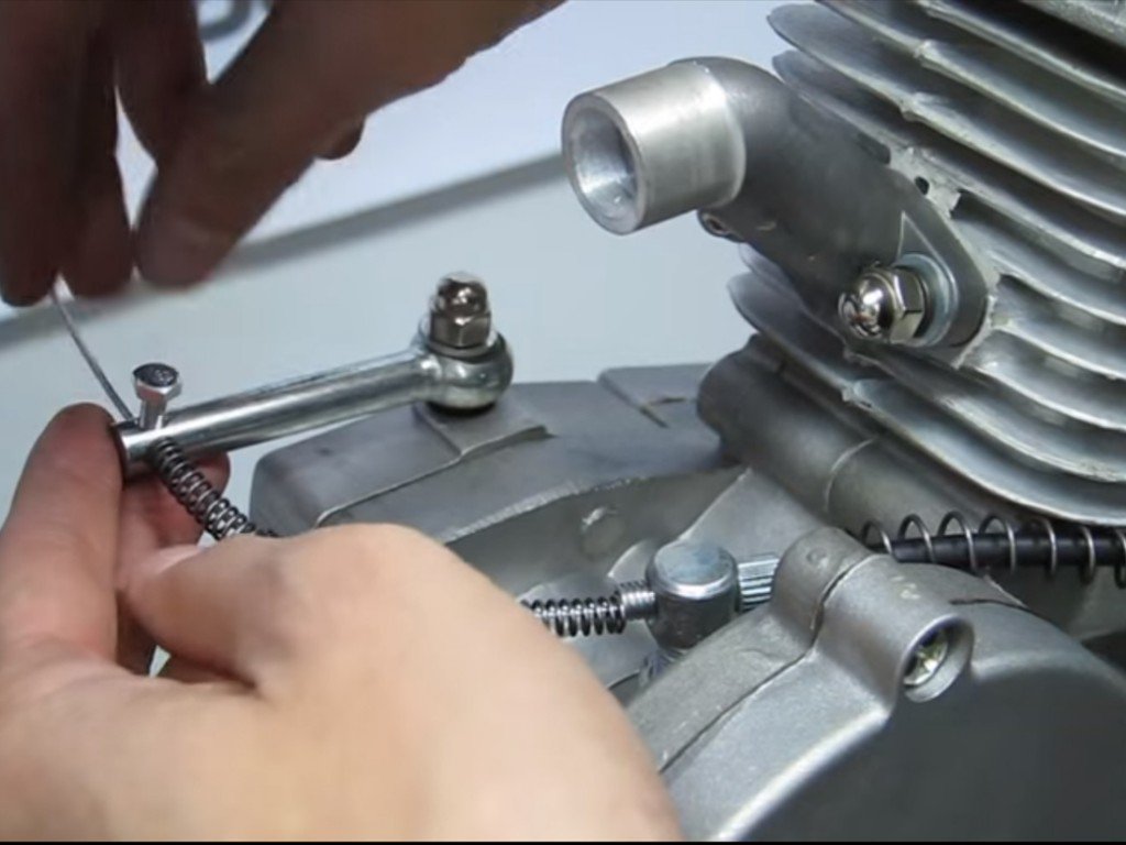
- Slide the heat shield spring over the opposite end of the cable, and slide the wire though the clutch base screw
- Slide the clutch spring over the wire, then slide the wire through the clutch arm on the engine (Note: loosen the clutch arm screw before sending the wire through the clutch arm)
- Align the clutch arm so it’s flush with the engine (i.e. it points straight back), tighten the tension of the clutch cable so it stays, then tighten down the clutch arm screw
With your clutch arm pulled in, you can pedal your bike like normal because the engine’s disengaged. Once you release the clutch lever, your engine will engage.
Chain Installation:
For easier installation of the chain, start by removing the clutch case cover (along with the clutch plate) and the drive sprocket case cover. Doing this will help the drive sprocket and clutch spin with ease. Then remove the master link from your chain
- Measure the chain on the rear and front sprockets, then remove any unnecessary links (you’ll need a motorcycle chain breaker to remove links). Note: you’ll want to leave .5” of slack on the chain so that it doesn’t snap
- Reinstall the master link
- Reinstall the case covers and components
- Install the pulley on your rear fork, and put the bottom portion of the chain on top of the plastic idle wheel
- Align the chain so that the top and bottom portions of the chain run along a straight path. If the chain is not straight it can slip off the sprockets and damage your spokes (and even you, if you’re not careful)
Throttle Installation: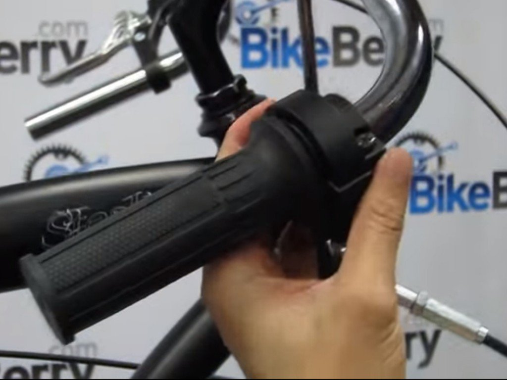
Start by dry fitting the throttle handle and kill switch on your handle bars, then mark where you’ll need to drill a ¼” hole in to the handle bar.
- Thread the “L” bracket end of the throttle cable in to your kill switch housing
- Slide the beaded end of the cable in to the cable port in the throttle grip
- Insert the grip in to the kill switch housing, then slip the grip on to the handle bars
- Line the pin from the top of the kill switch to the port you drilled, then screw the top and bottom portions of the kill switch together, forming your throttle and kill switch assembly
Carburetor Installation:
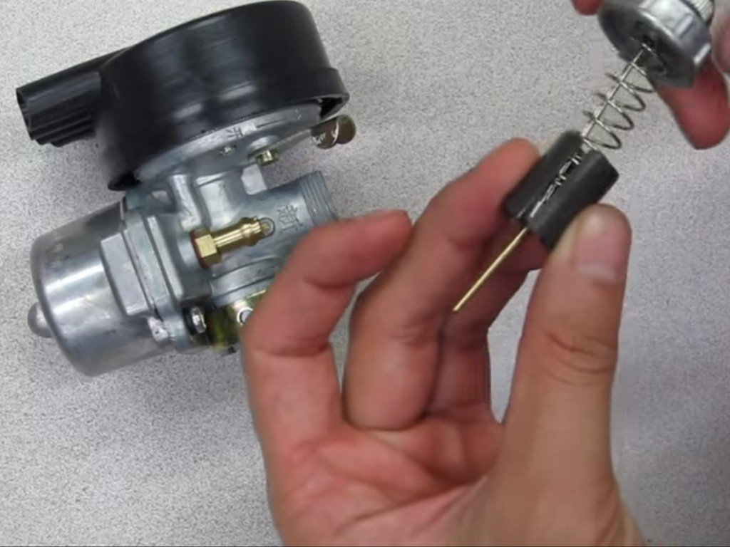
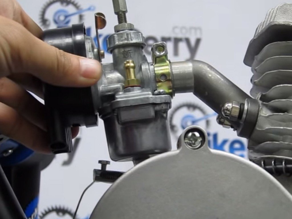 Start by going to the carburetor and removing the bottom end of the carburetor and remove the screw top, spring, plunger, jet needle (with c-clip attached), and the “e” washer.
- Start by now inserting the jet needle in to the plunger, then the “e” clip above that
- Stand the spring up in the plunger, then press down the screw top down on to the spring, which will compress the throttle components
- Thread the end of the throttle cable through the screw top, and in to the plunger
- Send the beaded end of the throttle cable in to the small port of the plunger (not the jet needle port), install, and let it go
- Insert your new throttle assembly back in to your carburetor. Note: Do not force the plunger in to the carburetor. If it does not easily slide in, this is a sign that it’s not aligned within the carburetor. Slowly turn the cable until you feel the plunger easily drop down in to the carb
- Screw the screw top back on
- Loosen carburetor mounting clamps, slide the carburetor over the manifold, tighten it around the manifold, and align the carburetor so that the throttle cable is pointed up and the float bowl is level with the ground
Electrical Wiring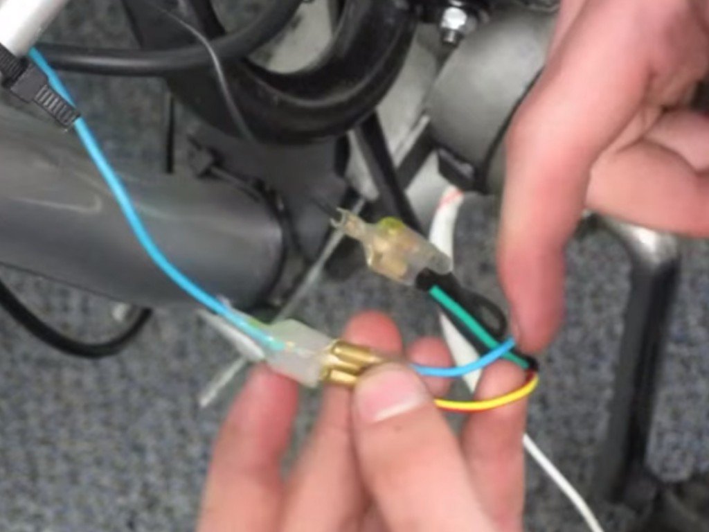
There are four components to your electric wiring: the magneto, the CDI, kill switch, and the spark plug. The spark plug, magneto, and now the kill switch are already installed, so all you need to install in the CDI. You can mount the CDI anywhere on your frame, as long as it’s close enough to the spark plug to connect to it.
Now that everything is ready to wire, let’s get down to it:
- Connect the black wire from the CDI to the black wire from the magneto, and the green wire from the kill switch. These are your ground wires that will complete the circuit
- Connect the blue wire from the CDI to the blue wire on the magneto, and the yellow/red wire from the kill switch
Note: kill switch wiring coloring will vary between engines and engine suppliers. These colors may not be your colors, but as long as you know which ground wires you have it’s only a process of elimination where your other wires are.
The Rest of Your Bike:
Now it’s time to install the rest of those components.
- Install the muffler on to the front of the motor head (opposite of the carburetor)
- Install the gas tank
- Line the tank up with the top bar, align the gas tank brackets under that bar, and fasten the tank to the bike
- Install the fuel valve in to the gas tank, connect the fuel line to the carburetor’s fuel jet, and connect the fuel line to the fuel valve
- To install the chain guard, slide the guard’s front bolt port over the long screw behind your drive sprocket case cover, then fasten it with a nut. Then use a zip-tie to fasten the other end to the frame (Do not let this interfere with the chain)
CONGRATULATIONS- You just installed your bike engine kit! Before riding, we recommend using a ratio of 6 oz to 1 gallon to break your motor in, then 4-5oz to 1 gallon after the motor is broken in. However, engines may vary, so consult the manufacturer for their recommended oil ratios.